Search
What is a Inverter?
The Inverter is a power control device that uses frequency conversion technology and microelectronics technology to control AC motors by changing the frequency of the motor's working power supply. The Inverter mainly consists of rectifier (AC to DC), filter, inverter (DC to AC), braking unit, driving unit, detection unit, microprocessor unit, etc. The Inverter adjusts the voltage and frequency of the output power supply by breaking the internal IGBT, providing the required power voltage according to the actual needs of the motor, thereby achieving energy conservation and speed regulation. In addition, the Inverter also has many protection functions, such as overcurrent, overvoltage, overload protection, and so on. With the continuous improvement of industrial automation, Inverter have also been widely used.
A Inverter is a device that converts industrial frequency power sources (50Hz or 60Hz) into AC power sources of various frequencies to achieve variable speed operation of the motor. The control circuit controls the main circuit, the rectifier circuit converts AC power into DC power, the DC intermediate circuit smooths and filters the output of the rectifier circuit, and the inverter circuit converts DC power back into AC power. For inverters such as vector controlled inverters that require a lot of computation, sometimes a CPU for torque calculation and some corresponding circuits are also required. Variable frequency speed regulation is achieved by changing the frequency of power supply to the stator winding of the motor.

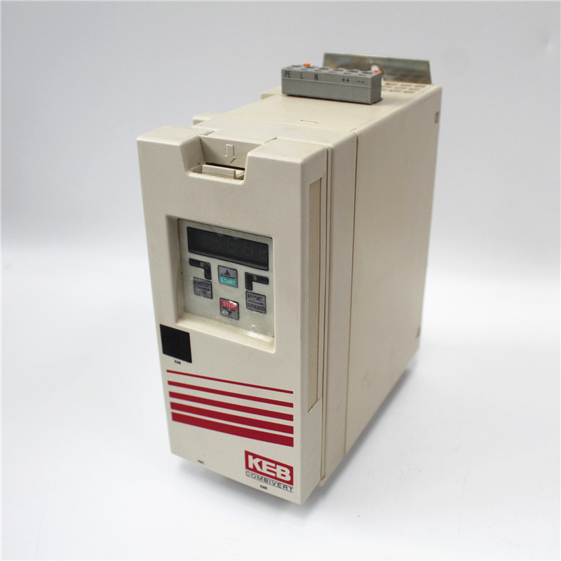
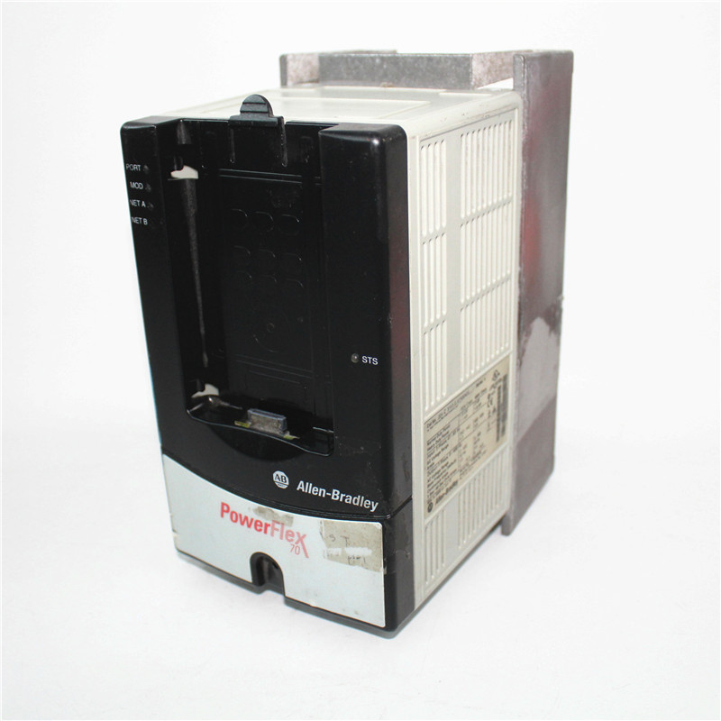
Our company has a large inventory, including different brands, such as Siemens Inverters, ABB Inverters, Yaskawa Inverters, Mitsubishi Inverters, Schneider Inverters, American AB Rockwell Inverter and German KEB Kobe Inverter.etc
Function of Inverter
There are various classification methods for Inverter, which can be divided into voltage type Inverter and current type Inverter according to the working mode of the main circuit; According to the classification of switch modes, it can be divided into PAM controlled Inverter, PWM controlled Inverter, and high carrier frequency PWM controlled Inverter; According to the working principle, it can be divided into V/f control Inverter, slip frequency control Inverter, vector control Inverter, etc; According to the classification of purposes, it can be divided into general Inverter, high-performance specialized Inverter, high-frequency Inverter, single-phase Inverter, and three-phase Inverter.
Troubleshooting of Inverter
With the continuous improvement of industrial automation, they have been widely used. So what are the common faults of Inverter and how can they be resolved?
Problem 1: Communication failure between the motherboard and PLC
Fault symptom:
1) The touch screen of the Inverter reports a communication fault between the motherboard and PLC, and the PPI cable receiving light RX light is off or not flashing. The power indicator lights on the motherboard are off. High voltage is still applied to the module input, and the module output is blocked.
2) The touch screen of the Inverter reports a communication fault between the motherboard and PLC, and the PPI cable transmission light TX light is off or not flashing.
3) The touch screen reports a communication fault between the motherboard and PLC, and the PPI cable power light POW is not on.
Fault cause:
1) During the operation of the Inverter, due to a malfunction in the power supply switch PW1 of the motherboard or the DC power supply on the motherboard, the power supply of the entire motherboard is lost, and the IGBT switch signal stops. Therefore, a communication failure between the motherboard and PLC is reported; Module blocking output; At the same time, due to the power loss of the motherboard, the fault trip signal cannot be sent out, and high voltage is continuously applied to the module.
2) The motherboard cannot receive the communication signal sent by the PLC, and there is a problem with the communication part of the PLC itself.
Resolvent:
1) Install an active isolation transmitter between the DCS given signal and the motherboard signal acquisition circuit.
2) Change the functional parameter of Inverter 117 (given frequency threshold) from 0 to 30, without the need to install an isolation transmitter.
Problem 2: The Inverter does not respond when given a frequency
The remote DCS provides a certain frequency, and the Inverter touch screen does not adjust the speed after receiving the frequency.
Fault cause:
When the PLC determines that the system is in the "remote control" mode, the main control can only receive remote 4-20ma signals for frequency adjustment. Therefore, the main reason for the DCS given frequency system not regulating speed is that 1) the control method (function number 207) accepted by the main control is incorrect; 2) The frequency setting mode (function number 208) in panel control mode is incorrect.
Resolvent:
1) Rotate the rotary button on the control cabinet door to set the function number 207 to 1, which is remote control mode.
2) Select the frequency setting mode under panel control mode, with function number 1, that is, analog input AI frequency setting.
Problem3: 'Please close the high voltage' issue
Fault symptom:
1) The Inverter changed from a "system ready" state to a "please turn on high voltage" state, and the process change delay was only set to 60 seconds. After disconnecting the high voltage for 60 seconds, the "please turn on high voltage" was uploaded to the DCS, and the operator re turned on the high voltage, causing the fuse of 16 modules to burn out.
2) Due to the user's refusal to introduce the "please switch on high voltage" status into the DCS system, the Inverter was disconnected due to other equipment failures. The operator did not delay the high-voltage switch for 300s according to regulations before switching on the high voltage again. Instead, they urgently switched on the high-voltage switch of the Inverter, resulting in the fuse of 16 modules being burned out.
Fault cause:
Due to the high voltage power outage of the Inverter, the power inside the capacitor in the module cannot be immediately discharged, which requires a certain amount of time. At this time, the high voltage is reconnected, causing a short circuit and burning the fuse.
Resolvent:
1) Set the time from the "System Ready" state to the "Please Close High Voltage" state to 300S.
2) On site installation and debugging must connect the "Please Close High Voltage" signal to the user's DCS system, and ensure that the thermal engineering performs interlocking protection in the closing circuit.
Problem 4: System output overcurrent and overload
Fault symptom:
1) During the normal operation of the Inverter, the system output overcurrent or output overload fault causes the Inverter to shut down due to a serious fault.
2) The Inverter shuts down due to system output overload or system overcurrent fault during the acceleration process.
3) The Inverter reported overcurrent during startup.
Fault cause:
1) The possible reasons for the sudden output overload or overcurrent of the Inverter during normal operation may be due to fluctuations in bus voltage, sudden increase in load startup, or a fault in the frequency conversion output current sampling circuit that causes excessive frequency conversion current collection.
2) Current sensor failure or motherboard signal acquisition circuit failure, resulting in incorrect operation of the Inverter.
3) The Invertern outputs overload or overcurrent during the acceleration process mainly because the acceleration time is too fast.
4) Due to the load during the start-up process of the Inverter (mainly due to the reverse action of the fan on the opposite side) being in a drooping state or the motor load being stuck.
Resolvent:
1) During the normal process, the sudden overload and overcurrent of the Inverter are mainly caused by confirming the cause of the trip. If it is caused by changes in the power grid or sudden load changes, the Inverter should be restarted. If it is caused by a fault in the Inverter acquisition circuit itself, the corresponding wiring and Hall sensor should be checked.
2) During the speed up process of the Inverter, if the system output is overloaded or the system overcurrent causes a malfunction and shuts down, the corresponding up and down speed up times should be modified, and the time should be set as large as possible.
3) Ensure that the fan load is at a standstill during startup; Modify the DCS startup logic of the fan, close all inlet and outlet dampers before starting the motor, and then open them after starting to avoid current impact; Start the power frequency first and then start the Inverter; Set the torque increase in the function number to increase the starting torque of the Inverter.
Problem 5: Module DC overvoltage
Fault symptom:
1) During the shutdown and speed reduction process of the Inverter, multiple module DC overvoltage faults occurred, causing the user's high-voltage switch to trip.
2) The user's bus voltage is too high. The actual bus voltage of the 6KV power supply is above 6.3KV, and the actual bus voltage of the 10KV power supply is above 10.3KV. When the bus voltage is applied to the Inverter, the module input voltage is too high, and the module reports DC bus overvoltage.
3) During the startup process of the Inverter, approximately until it reaches 4HZ, the DC bus of the Inverter is overvoltage.
Fault cause:
1) During the shutdown process of the Inverter, the speed reduction time is too fast, causing the motor to be in the generator state. The motor feeds back energy to the DC bus of the module, generating a pump up voltage, which leads to a high voltage on the DC bus.
2) Due to the factory standard wiring of on-site transformers being 10KV and 6KV, if the bus voltage exceeds 10.3KV or 6.3KV, it will cause the output voltage of the transformer to be too high, resulting in an increase in the bus voltage of the module and causing overvoltage.
3) Different phase modules at the same position have fiber optic connections reversed (such as A4 and B4 fiber optic connections reversed), resulting in overvoltage in their phase voltage output.
Resolvent:
1) Extend the up/down time and down time appropriately.
2) Raise the overvoltage protection point inside the module to 1150V.
3) Change the short-circuit terminal of the transformer to 10.5KV (6.3KV) when the user voltage reaches 10.3KV (6KV) or above.
4) Check if the optical fiber is inserted incorrectly and correct the incorrect fiber.
Problem 6: Module communication failure
Fault symptom:
During the operation of the Inverter, there is a serious fault that trips and shuts down, and the touch screen reports a module communication fault.
Fault cause:
1) The input fuse, rectifier bridge, and charging resistor of the module are burnt out, causing the module control to lose power and communication to be unable to proceed.
2) The optical communication sub board on the motherboard is faulty or protected by the protection diode of the communication circuit power supply.
3) The connecting optical fiber is inserted in the wrong position or the optical fiber is broken or damaged.
4) The output voltage of the power board in the module is abnormal or there is no output, causing communication interruption in the module.
Resolvent:
1) Open the module cover and replace any damaged components such as fuses and charging resistors in the module.
2) Replace the damaged optical circuit board or protective diode.
3) The optical fiber is connected normally according to the markings, and if the optical fiber is damaged, it should be replaced.
4) Replace the module power board.

Our company is a global supplier of new and used surplus products. It has grown to become one of the largest wholesale suppliers of industrial and automation products, serving customers worldwide 24 hours a day. We offer hundreds of thousands of parts and strive to source and supply your parts at a fraction of the retail cost.